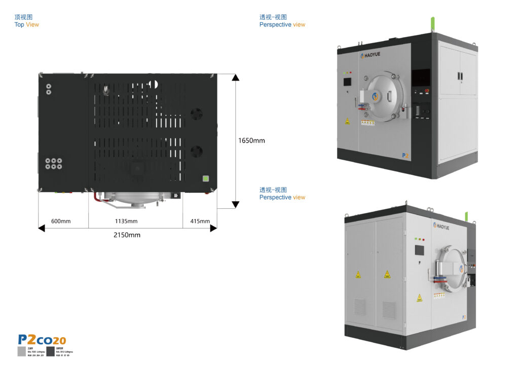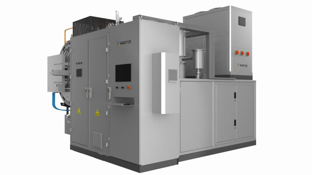
A MIM debinding and sintering furnace is a vacuum or hydrogen-atmosphere furnace that removes the polymer binder from a metal injection moulded part and sinters that part to near-full density, either as one programmed thermal cycle or as two linked steps. In our experience the sintering hold is the easy part — the two hours between roughly 150 °C and 600 °C decide whether the batch leaves at 7.8 g/cm³ or leaves with blisters, sink marks and a carbon number nobody can explain.
That is why we ask for the feedstock data sheet before we ask for the temperature. A furnace can be built to any reasonable ceiling; it cannot rescue a binder system that was never designed to leave a 6 mm wall at a controlled rate.

What a MIM furnace actually has to do
Metal injection moulding combines four process stages, and the furnace owns the last two. The feedstock — metal powder typically below 20 µm, compounded with a multi-component binder at a powder loading typically near 60 vol% — is moulded, then debound, then sintered.
The binder is not one material. Production feedstocks usually contain a backbone polymer that holds shape until late in the cycle and one or two filler components that leave early and open a pore network for the rest to escape through. That design is deliberate, and it dictates the shape of the thermal profile: each component needs a hold near its decomposition range, and the ramp between those holds must be slow enough that the internal vapour pressure never exceeds what the pore network can vent.
Debinding itself splits into two industrial families:
- Solvent or catalytic debinding first, thermal debinding second. Part of the binder is dissolved or catalytically cracked outside the furnace, which opens the porosity; the furnace then removes the backbone. Faster, but it adds a wet step and a handling step.
- Purely thermal debinding in the furnace. Slower, single-equipment, and the route most batch producers choose when part geometry is moderate and the alloy is not oxygen-sensitive.
A MIM debinding and sintering furnace is therefore specified around two thermal stages that share one pumping system, one exhaust path and one control record. That shared hardware is the practical difference from running a debinding oven and a sintering furnace side by side — and it is also why an undersized exhaust on the debinding side shows up as a sintering defect.
Sintering follows at a temperature that depends on the alloy — many stainless and iron-nickel MIM cycles sit in the 1,250–1,380 °C band, holding typically 60–120 minutes, with linear shrinkage typically 15–20%. Those are industry-typical figures, not catalogue values; the actual numbers come from your feedstock supplier’s dilatometry.
How the cycle works, stage by stage
Stage 1 — Purge, leak check, and the reason both matter
MIM loads have an unusually large surface area for their mass: fine powder, thin sections, often hundreds of parts per tray. That surface holds air and moisture, and it releases them slowly. A leak-up test after every door opening is not bureaucracy — a marginal flange seal that would be irrelevant for a dense billet load will show up as an oxygen rise exactly when the binder is trying to leave.
For hydrogen cycles, dew point is the number to watch. Moisture in the gas is both an oxidiser for the alloy and a reactant that shifts the carbon balance.
Stage 2 — Thermal debinding, roughly 150–600 °C
This is where yield is decided. Two removal mechanisms run in parallel: capillary wicking into the setter powder bed, and evaporation or thermal decomposition into the sweep gas.
Three variables have to be controlled together:
- Ramp rate. Typically 0.5–2 °C/min through the decomposition window. Faster saves hours and costs batches.
- Partial pressure of the sweep gas. Too low and the binder boils inside the part, producing blisters and internal voids. Too high and the vapour never leaves the chamber efficiently — it condenses in the exhaust line and leaves carbon behind in the part.
- Hold placement. A hold that is too short at the first decomposition peak pushes unremoved filler into the second window, where the escaping path is already closing.
The most common field failure we are asked to diagnose is not a furnace fault at all: it is a 300 °C hold that was shortened to improve throughput, followed three weeks later by a cracking problem that appears at 900 °C.
Stage 3 — Switch to the sintering atmosphere
Once the backbone has left, the atmosphere changes job. In vacuum, the target is a low residual oxygen partial pressure so that oxide films on the powder surfaces can be reduced or dissolved; the 6.7×10⁻³ Pa figure on our molybdenum-heater platforms is a high-vacuum rating that requires a diffusion pump or a turbomolecular pump backed by a mechanical pump — a mechanical pump alone reaches only the rough-vacuum class around 1 Pa and is not sufficient for this step.
In hydrogen, the mechanism is chemical rather than mechanical: H₂ reduces surface oxides and reacts with residual carbon, and the products are carried out of the chamber. The H series vacuum hydrogen furnace is built for exactly that combination — molybdenum elements, 6.7×10⁻³ Pa, 1000/1300 °C, with vacuum and hydrogen in one chamber and a 1–15 °C/min ramp to 1300 °C.
Stage 4 — Sintering hold
On our molybdenum-heater MIM platform the ceiling is 1000/1300 °C, which covers the lower part of the stainless and iron-nickel band. Uniformity is stated as ±5 °C on a five-point survey at 1000 °C held for one hour. Treat that as a baseline, not a guarantee at every load: it is measured on a characterised empty-ish chamber, and a dense tray of parts changes the thermal map. A shrinkage survey across the tray is the honest verification, because shrinkage is what your tooling was cut for.
Stage 5 — Cooling
Cooling is a metallurgical step, not dead time. In 316L, the 450–850 °C window is where chromium carbides can precipitate at grain boundaries, and a slow uncontrolled cool through it trades corrosion resistance for nothing. Our platforms offer optional 2 bar gas fast cooling to shorten that transit; the trade-off is thermal gradient across the load, which shows up as distortion on thin walls.
Stage 6 — Verification
Density by Archimedes, carbon and sulphur by combustion, dimensions on a first-off sample, and metallography where the application is medical or aerospace. If the carbon number drifts batch to batch with everything else fixed, look at the debinding exhaust path and the setter condition before you touch the sintering recipe.
Key parameters to specify on an RFQ
| Parameter | Why it matters in MIM | Our listed range for this platform |
|---|---|---|
| Maximum temperature | Sintering temperature plus margin for alloy development | 1000/1300 °C (molybdenum-heater platform) |
| Ultimate vacuum | Pump-package class, not a chamber property | 6.7×10⁻³ Pa with diffusion or molecular pump |
| Ramp rate | Debinding window is far slower than sintering window | 1–15 °C/min up to 1300 °C |
| Temperature uniformity | Drives shrinkage consistency across the tray | ±5 °C, five-point survey at 1000 °C for 1 h |
| Atmosphere | Carbon and oxygen balance | Vacuum, with hydrogen debinding optional on the V MO platform; vacuum + H₂ on the H series |
| Cooling | Carbide precipitation window, distortion | Optional 2 bar gas fast cooling |
| Useful chamber | Batch envelope and tray count | 400×400×600 up to 1000×1000×1400 mm; Ø650×1200 and Ø650×3200 mm vertical |
| Control | Recipe repeatability and traceability | Industrial PC + PLC + PID, multi-zone control |
Machines we build for this duty
The molybdenum-heater V series is the workhorse for MIM and CIM sintering where a carbon-free hot zone matters. All models share the same 6.7×10⁻³ Pa high-vacuum class, 1000/1300 °C ceiling and 1–15 °C/min ramp, and hydrogen debinding is available as an option.
| Model | Chamber (mm) | Ultimate vacuum | Max temperature | Ramp |
|---|---|---|---|---|
| V4M013 | 400×400×600 | 6.7×10⁻³ Pa | 1000/1300 °C | 1–15 °C/min |
| V6M013 | 600×600×900 | 6.7×10⁻³ Pa | 1000/1300 °C | 1–15 °C/min |
| V7M013 | 700×700×1000 | 6.7×10⁻³ Pa | 1000/1300 °C | 1–15 °C/min |
| V8M013 | 800×800×1200 | 6.7×10⁻³ Pa | 1000/1300 °C | 1–15 °C/min |
| V10M013 | 1000×1000×1400 | 6.7×10⁻³ Pa | 1000/1300 °C | 1–15 °C/min |
Where the cycle needs a genuine reducing atmosphere rather than vacuum with a hydrogen option, the H series vacuum hydrogen furnace provides it in the same temperature class:
| Model | Structure | Chamber (mm) | Heating element | Loading | Max temperature |
|---|---|---|---|---|---|
| H4M013 | Horizontal | 400×400×600 | Mo | Side | 1000/1300 °C |
| H6M013 | Horizontal | 600×600×900 | Mo | Side | 1000/1300 °C |
| H7M013 | Horizontal | 700×700×1000 | Mo | Side | 1000/1300 °C |
| H8M013 | Horizontal | 800×800×1200 | Mo | Side | 1000/1300 °C |
| HV6S/120 | Vertical | Ø650×1200 | Mo | Bottom | 1000/1300 °C |
| HV6S/320 | Vertical | Ø650×3200 | Mo | Top | 1000/1300 °C |
The two vertical models are worth a second look when parts are long and slender — surgical instruments, rifle components, slender shafts — because hanging or standing a tall batch avoids the tray sag that flat loading introduces.
Debinding and sintering in one cycle, or two?
Both routes are legitimate, and the choice is usually about part mix rather than technology.
| Route | How it runs | Strength | Where it hurts |
|---|---|---|---|
| Single-cycle, integrated debinding + sintering | One recipe, one furnace occupancy, atmosphere never opened | No oxide or handling exposure between steps; one traceable record | Binder vapour must be managed inside the sintering furnace; very thick sections still need a slow, dedicated debinding |
| Two-step: debinding oven then vacuum sintering furnace | Separate equipment, parts transferred | Each step can be tuned and run at its own throughput; debinding furnace stays clean | Transport and air exposure between steps; two recipes to qualify; double logistics |
| Hydrogen continuous or bell-type | Continuous flow, high volume | Throughput on a narrow, stable part family | Limited flexibility, hydrogen safety infrastructure, long changeover |
| SPS / FAST | Pulsed current plus uniaxial force | Minutes, fine grain, alloy screening | 1 Pa mechanical-pump vacuum class and 50–400 kN press; a development tool, not a MIM production line |
| Sintering plus HIP | Vacuum sinter, then hot isostatic press | Closes residual porosity for fatigue-critical parts | 100/150/200 MPa equipment cost; only justified where porosity is a design driver |
For most job shops the integrated route wins on traceability and handling, provided the furnace has a proper exhaust and condensate strategy. That is the configuration we build most often as a MIM debinding and sintering furnace: molybdenum hot zone, 6.7×10⁻³ Pa high vacuum, hydrogen debinding available as an option rather than as a second machine. For a plant running one alloy at high volume, a dedicated debinding line plus a large sintering furnace usually beats it on cost per part.
Applications
- Stainless steel MIM (316L, 17-4PH, 304L): the volume application. Carbon control is the whole game for corrosion resistance.
- Iron-nickel and low-alloy steels: dimensional stability across the tray matters more than the absolute density.
- Cobalt-chrome: dental frameworks and medical instruments, where metallographic cleanliness is inspected, not assumed.
- Tungsten heavy alloy and refractory metal parts: higher sintering temperatures push you off the 1300 °C platform, see the limitations below.
- Kovar, Invar and soft magnetic alloys: hydrogen sintering is often the difference between specified magnetic properties and almost-specified ones.
- Ceramic injection moulding: the G series integrates positive-pressure dewaxing, vacuum debinding, vacuum sintering, partial-pressure sintering and pressure sintering in one machine, at 10 Pa vacuum class and 6/10 MPa gas pressure, up to 1600/2000 °C.
When this furnace is the wrong choice
We would rather say this early than argue about it after a purchase order.
- Section thickness above roughly 10 mm. Binder has to diffuse out through the part; thick sections need very long debinding and often a dedicated debinding step. A single-cycle recipe will blister them.
- Alloys that need 1,350–1,400 °C or more. Our molybdenum platform stops at 1300 °C. Going higher means the graphite-heater V series at 2000/2400 °C — and then carbon becomes a variable you have to manage through atmosphere and setter choice, because a graphite hot zone is a carbon source at temperature.
- Titanium and aluminium-containing alloys where oxygen is a design limit. We will not promise a sub-1,000 ppm oxygen result from a sintering furnace. Vacuum quality helps; feedstock oxygen, powder surface area and handling usually dominate.
- Pressure-assisted densification. A sintering furnace has no press. If the specification calls for pressure, the conversation moves to the P series hot press at 2200 °C and 100–1200 t, to SPS for small samples, or to the I series HIP at 100/150/200 MPa.
- Very low volumes. Below a few thousand parts a year, machining or investment casting usually wins on total cost, and MIM tooling amortisation is the reason.
- Feedstock with a poorly designed binder system. No thermal profile fixes a feedstock whose backbone decomposes in the same window as its filler.
If you are specifying a furnace for an existing MIM line, send us the feedstock data sheet, the maximum section thickness and the alloy specification — those three answers are usually enough for a first view on whether a single-cycle platform fits or whether the route needs two steps.
Related equipment
For a single-cycle platform, the debinding and sintering furnace range for MIM covers integrated dewaxing and vacuum sintering. Where the hot zone must stay carbon-free, the molybdenum-heater vacuum sintering furnace range runs 6.7×10⁻³ Pa up to 1000/1300 °C, and when the cycle needs a true reducing atmosphere, the vacuum hydrogen atmosphere sintering range puts vacuum and H₂ in the same chamber.
FAQ
What is a MIM debinding and sintering furnace?
It is a vacuum or hydrogen-atmosphere furnace that removes the polymer binder from a metal injection moulded part and sinters it to near-full density, in one programmed cycle or in two linked steps.
Can debinding and sintering really run in the same furnace?
Yes, and it is common. The requirement is a controlled exhaust path for binder vapour, a partial-pressure strategy in the 150–600 °C window, and a recipe that treats the two stages as one thermal history rather than two unrelated programs.
What vacuum level does MIM sintering need?
It depends on the alloy and the carbon specification. A high-vacuum class of 6.7×10⁻³ Pa, delivered by a diffusion or molecular pump, is what our molybdenum-heater platform is rated for; a mechanical pump alone reaches the rough-vacuum range around 1 Pa and is generally not enough for stainless MIM.
Hydrogen or vacuum for MIM?
Vacuum for carbon-sensitive stainless where you want to keep the atmosphere inert, hydrogen where you need to reduce oxides and strip residual carbon. Dew point control decides whether hydrogen helps or oxidises.
Why does our carbon content drift between batches?
Usually the debinding exhaust, not the sintering hold: condensate in the line, a shortened hold, or contaminated setters. Check those before changing the sintering recipe.
What is the maximum part size?
It is set by debinding, not by the chamber. Our largest molybdenum platform is 1000×1000×1400 mm, but a part with 15 mm walls will not debind cleanly in a single cycle regardless of chamber size.