





A vacuum brazing furnace is a batch furnace that joins an assembly by melting a filler metal inside a controlled high-vacuum or hydrogen atmosphere — in our H series, 6.7 × 10⁻³ Pa with a molybdenum (MO) hot zone rated 1000 / 1300 °C — so that a component carrying dozens of separate joints is bonded in a single thermal cycle, without flux, without a melted parent metal, and without a heat-affected zone. Welding creates a joint by melting the parts themselves; brazing creates one by melting something else, and that single distinction is why the furnace — not the torch — decides whether the joint is continuous.
Most teams that go looking for a vacuum brazing furnace are not shopping for heat. They already know the temperature. What they need is a machine that can hold a residual oxygen partial pressure low enough that a molten filler will wet a real production surface, on parts that have been handled, stacked, fixtured and possibly stored for weeks.
This article covers what the vessel has to deliver, the six stages of a cycle, and the parameters worth writing into a purchase specification.

What Is a Vacuum Brazing Furnace?
A brazing furnace has to deliver four things at the same time. Any one of them missing turns a good filler into a bad joint:
| Requirement | Why it decides the outcome | H series specification |
|---|---|---|
| High vacuum | Wetting depends on the oxide state of the surface, and oxide state depends on the oxygen partial pressure above the part — not on “how clean the part looked” | 6.7 × 10⁻³ Pa (diffusion / molecular pump class) |
| An isothermal hot zone | Capillary flow needs the whole joint at the same temperature; a hot spot drains the filler away from the cold end | Molybdenum (MO) heating element, 1000 / 1300 °C |
| A hydrogen option | Vacuum prevents new oxide from forming. A reducing atmosphere can remove oxide that is already there — a different job | Vacuum and hydrogen integrated in one vessel |
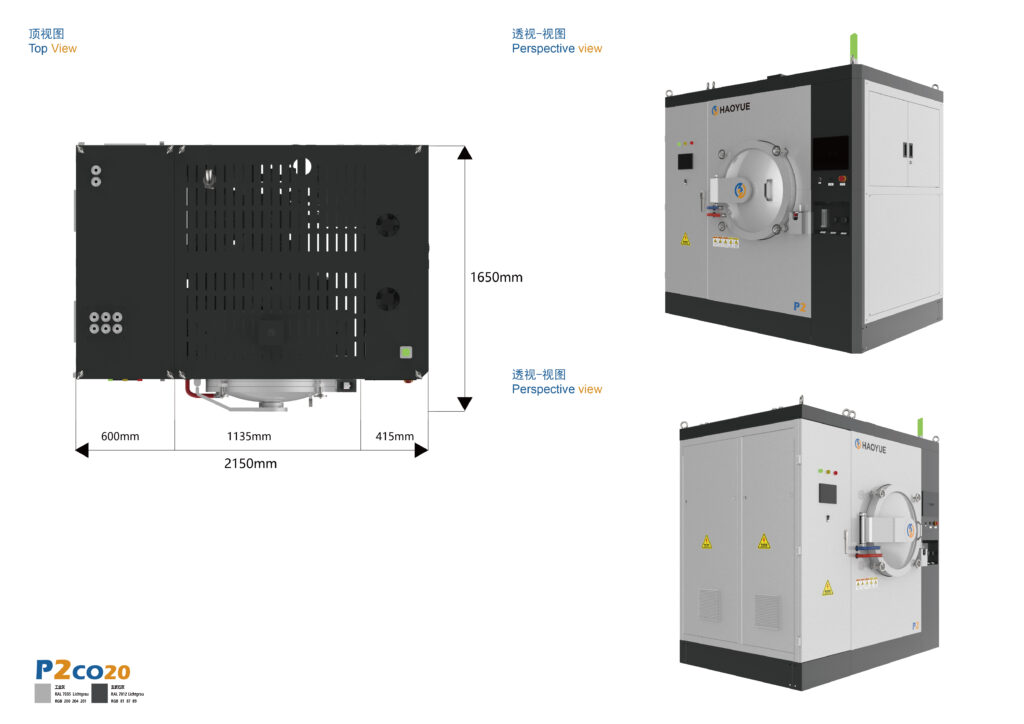
| Enough usable volume | Brazing economics come from amortising one pump-down and one ramp across many joints | 400 × 400 × 600 mm up to 800 × 800 × 1200 mm; vertical Φ650 × 1200 mm and Φ650 × 3200 mm |
Two clarifications worth making before a specification is written.
First, the vacuum figure is a pump-group configuration class, not a precision vanity number. 6.7 × 10⁻³ Pa is the high-vacuum class reached with a diffusion or molecular pump. A furnace quoted at 1 Pa or 10 Pa is running on mechanical pumping only and is intended for a different duty. If your process logic needs genuine high vacuum at the joint, say so at enquiry stage, because that decision fixes the whole machine.
Second, the chamber number that matters is the usable volume — the volume left after the hot zone, the fixture and the loading table are in place. A 800 × 800 × 1200 mm vessel does not accept an 800 × 800 × 1200 mm assembly.
How Vacuum Brazing Works — Stage by Stage
Stage 1 — Cleaning, gap control and assembly
Vacuum brazing has no flux, and that is both the advantage and the discipline. Nothing in the process will dissolve a fingerprint, a cutting-fluid residue or an oxide film. Plate-fin and tube-and-header assemblies are typically tacked, pinned or fixture-clamped at a joint clearance in the 0.02–0.10 mm band — tight enough for capillary force to pull the filler through, wide enough for the filler to actually flow.
Stage 2 — Pump-down and outgassing
The pump-down is not a waiting period; it is a process step. Water vapour and hydrocarbon residues desorb from the part, the fixture and the vessel walls, and most of them leave in the 200–400 °C window. Rushing through that window traps vapour at the joint and shows up later as voids along the bond line. A holding segment during heat-up is therefore standard practice.
Stage 3 — Heating to the filler’s flow temperature
Our H series ramps at 1–15 °C/min up to 1300 °C. That range is a decision, not a limitation. A fast ramp on a steel-to-steel assembly is often harmless. The same ramp across a ceramic-to-metal assembly — alumina or aluminium nitride sealed to copper, Kovar or a nickel-iron alloy — will crack the ceramic, because the differential expansion is resolved by stress rather than by time. Above the filler liquidus, the soak is typically held 20–50 °C above it, long enough for capillary flow and short enough to limit interdiffusion between the filler and the base metal.
Stage 4 — Soak: melt, wet, flow
This is the stage people picture, and it is the shortest. The hold is typically 5–30 min at temperature for a filler that flows well; nickel-based fillers on stainless steel and superalloys need the longer end, silver-based fillers on copper and brass the shorter. The observable end point is not a timer — it is a filler fillet that has formed on both sides of the joint.
Stage 5 — Controlled cooling
Cooling is the stage that gets designed last and causes the most rework. The filler must solidify while both members are still dimensionally stable. Where the joint is between dissimilar materials, the cooling ramp is set by the member with the highest coefficient of thermal expansion, not by the largest mass. Forced cooling is deliberately avoided at this point in a brazing cycle for exactly this reason.
What changes when you switch to hydrogen
Our H series runs vacuum and hydrogen in the same vessel, and the switch is not cosmetic. Vacuum protects passively — no oxygen, so no new oxide forms. Hydrogen protects actively: copper, nickel and iron oxides are chemically reduced, which is why stainless-steel and copper assemblies can be brazed flux-free. The controlling variable is the moisture budget — the dew point of the gas reaching the work — and that is a measurement and control problem, not a gas-supply problem. Hydrogen is also unforgiving to alloys containing high-vapour-pressure elements, and it requires purge sequencing, exhaust handling and interlock hardware engineered into the machine rather than added later.
Key Parameters — What to Put in the Specification
| Parameter | Our H series | What it actually controls | Question worth asking a supplier |
|---|---|---|---|
| Ultimate vacuum | 6.7 × 10⁻³ Pa | Oxygen partial pressure at the joint; filler wetting | Which pump set is included, and what leak rate is guaranteed at that level? |
| Maximum temperature | 1000 / 1300 °C | Which filler classes are addressable | Is the rating for the hot zone or for the work zone? |
| Heating rate | 1–15 °C/min (to 1300 °C) | Thermal gradients in dissimilar joints | Can the profile differ between the vacuum stage and the hydrogen stage? |
| Atmosphere | Vacuum + hydrogen, one vessel | Passive vs. active oxide control | How is dew point monitored and recorded during the hydrogen stage? |
| Chamber (horizontal) | 400 × 400 × 600 / 600 × 600 × 900 / 700 × 700 × 1000 / 800 × 800 × 1200 mm | Load size and stacking height | What is the usable volume inside the hot zone with fixture fitted? |
| Chamber (vertical) | Φ650 × 1200 / Φ650 × 3200 mm | Long, shaft-like and tubular assemblies | How is the load supported, and does the support conduct heat away? |
| Loading direction | Side (horizontal models) / bottom, top (vertical models) | Fixturing strategy and gravity-induced distortion | Which surface are the critical joints resting on? |
Models We Build — H Series Vacuum Hydrogen Furnace
| Model | Structure | Chamber (mm) | Heater | Loading | Ultimate vacuum (Pa) | Max temperature (°C) |
|---|---|---|---|---|---|---|
| HV6S/120 | Vertical | Φ650 × 1200 | MO | Bottom | 6.7 × 10⁻³ | 1000 / 1300 |
| HV6S/320 | Vertical | Φ650 × 3200 | MO | Top | 6.7 × 10⁻³ | 1000 / 1300 |
| H4M013 | Horizontal | 400 × 400 × 600 | MO | Side | 6.7 × 10⁻³ | 1000 / 1300 |
| H6M013 | Horizontal | 600 × 600 × 900 | MO | Side | 6.7 × 10⁻³ | 1000 / 1300 |
| H7M013 | Horizontal | 700 × 700 × 1000 | MO | Side | 6.7 × 10⁻³ | 1000 / 1300 |
| H8M013 | Horizontal | 800 × 800 × 1200 | MO | Side | 6.7 × 10⁻³ | 1000 / 1300 |
How to read this table: the horizontal, side-loading models suit flat stacks, plate-fin cores and manifold assemblies, where the load is wide and shallow. The vertical models exist for parts long relative to their section — tubular assemblies, shafts and sealing components — up to 3200 mm. Choosing between the two is usually a fixturing decision before it is a capacity decision.
Vacuum Brazing vs. Other Joining Routes
| Route | How the joint forms | Typical process window | Distortion / HAZ | Geometry freedom | Where it wins |
|---|---|---|---|---|---|
| Vacuum brazing (H series) | Filler melts and is drawn into the gap by capillary action | Up to 1300 °C; 6.7 × 10⁻³ Pa | Very low; entire load heated uniformly, non-melted base metal | Any geometry that fits the chamber; many joints per cycle | Multi-joint assemblies, thin-wall and plate-fin structures, ceramic-to-metal |
| Hydrogen-atmosphere brazing (same H series) | Same mechanism, active reducing atmosphere | Same window; dew point is the control variable | Very low | Same | Copper, nickel and stainless assemblies needing oxide removal without flux |
| Diffusion bonding (D series) | Solid-state; bond forms by atomic diffusion under pressure, with or without an interlayer | Up to 1400 °C; 6.7 × 10⁻³ Pa; mechanical pressure applied | Low, but pressure and flatness are mandatory | Constrained by press geometry and flat mating faces | Dissimilar metals, joints that must match parent-metal properties, no-filler requirements |
| Hot pressing (P series) | Simultaneous uniaxial pressure and temperature consolidate a powder or preform | Up to 2200 °C; 100–1200 ton; vacuum configuration depends on pump set | Uniaxial; density gradients possible | Set by die and ram, not by free geometry | Powders, composites, near-net shapes where pressure must exceed what gas or capillary can deliver |
| Fusion welding (TIG / electron beam) | Parent metal is melted locally | Local melt, no bulk heating | Higher; local heat-affected zone and residual stress | Free-form, unrestricted size | Structural joints on thick sections where a fusion bond is required |
The decision that catches people out is the middle row: brazing and diffusion bonding are often treated as interchangeable because both are “vacuum joining”. They are not. Diffusion bonding needs pressure and produces a joint without a filler; brazing needs a capillary gap and produces a joint with one. Where the parent metal is itself heat-treated to a specific temper, the brazing temperature — not the furnace — sets whether the part survives with its properties intact.
Applications Where a Batch Brazing Furnace Pays
- Heat exchangers and plate-fin stacks. Hundreds of joints in one load, no flux residue inside the channels, and no cleaning operation afterwards — the reason vacuum brazing became the default for compact cores.
- Ceramic-to-metal and glass-to-metal sealing. Alumina and aluminium nitride components sealed to copper or Kovar, and glass seals, where the joint must hold vacuum rather than merely hold load.
- Vacuum and electrical components. Feedthroughs, interrupter bodies and target assemblies — parts whose function fails if the joint is porous.
- Tool, die and wear assemblies. Carbide inserts and wear pads brazed to steel bodies, usually on a filler that flows below the tempering temperature of the body.
- Metallisation and pre-brazing preparation. The same vessel performs the metallisation step, because it is the same requirement — a clean, reduced surface.
- Aerospace and power-generation assemblies. Honeycomb seals, stator and vane assemblies and thin-wall structural elements where welding distortion is unacceptable.
Limitations — When a Vacuum Brazing Furnace Is the Wrong Choice
We would rather say this at enquiry stage than after a purchase order.
- Above 1300 °C it is out of range. Brazing filler metals that require a higher hold, and refractory-metal joining that demands it, are a different hot zone — not a setting on this one.
- Alloys with volatile elements fight the vacuum. Materials containing high-vapour-pressure elements deplete from the surface while the filler is still flowing, so the atmosphere decision must be revisited before the temperature decision.
- It cannot rescue a dirty part or a bad gap. There is no flux to compensate and no pressure to close a gap that is too wide. Cleaning and gap control are prerequisites, not steps the furnace performs.
- Aluminium brazing is a different discipline. Flux-free aluminium joining depends on its own oxide-removal mechanism and a very tight moisture budget, and should not be folded into a general brazing specification.
- Not every base metal tolerates the filler’s temperature. A copper-based filler puts the whole assembly at a temperature many heat-treated alloys will not survive. If the base metal’s temper is the binding constraint, brazing may be the wrong process even when it is technically possible.
- Low-volume single joints are uneconomic. The economics come from amortising a pump-down and a ramp across a full load. For one joint at a time, an induction or resistance route will be cheaper.
- Small thin sections can be eroded. Extended holds let molten filler dissolve base metal, and fine fins are the first to suffer. Filler volume and hold time are design parameters, not operator preferences.
- Hydrogen mode carries an engineering obligation. Purge sequencing, exhaust handling and interlocks are part of the machine specification; a furnace described as “vacuum and hydrogen” without that hardware is incomplete.
FAQ
Is vacuum brazing the same as hydrogen brazing?
No. Both can be performed in the same vessel — our H series does both — but they work differently. Vacuum protects by removing oxygen so no new oxide forms; hydrogen actively reduces existing copper, nickel and iron oxides. Vacuum suits materials that react with hydrogen or contain volatile elements; hydrogen suits stainless steel and copper assemblies that need oxide removal without flux. The control variable for hydrogen is dew point.
What joint clearance should I design for?
Typically 0.02–0.10 mm for a filler that flows by capillary action, and it must be consistent along the joint. Too tight and the filler cannot enter; too wide and capillary force is too weak to pull it through. The correct value depends on the specific filler and the base metals, so it should be confirmed against the filler supplier’s data rather than assumed.
Can I braze ceramic to metal in the same furnace?
Yes. Ceramic-to-metal sealing is one of the core applications of a vacuum hydrogen furnace, because it needs both a clean reduced surface and a slow, controlled ramp — the differential expansion between a ceramic and a metal has to be resolved by time rather than by stress. Our H series offers 1–15 °C/min up to 1300 °C, and a molybdenum hot zone, which is the combination this work needs.
Is 1300 °C enough for nickel-based brazing filler metals?
For most of them, yes — nickel-based fillers for stainless steels and superalloys are typically applied in the 1000–1200 °C range, which the H series covers with margin. The limit appears with filler metals or base-metal combinations that need to go higher; those belong to a different furnace class and should be raised separately.
Can brazing be combined with the sintering or metallisation cycle?
In principle it can be sequenced in one vessel when the temperature windows overlap, and our H series handles metallisation and brazing for the same reason — both require a clean, oxide-free surface. In practice the constraint is the base metal: whichever step needs the highest temperature sets the thermal history for everything in the load.
How do I decide between brazing and diffusion bonding?
Start from whether a filler is acceptable. If the joint must behave like the parent metal and no filler can be tolerated, diffusion bonding — up to 1400 °C with applied pressure in our D series — is the route. If the assembly has many joints, thin walls, or mixes a ceramic with a metal, brazing is usually the practical answer, because it needs no pressure and reaches every joint in the load at once.
Related equipment: H Series Vacuum Hydrogen Furnace · Vacuum Sintering Furnace · P Series Graphite Vacuum Hot Pressing Furnace