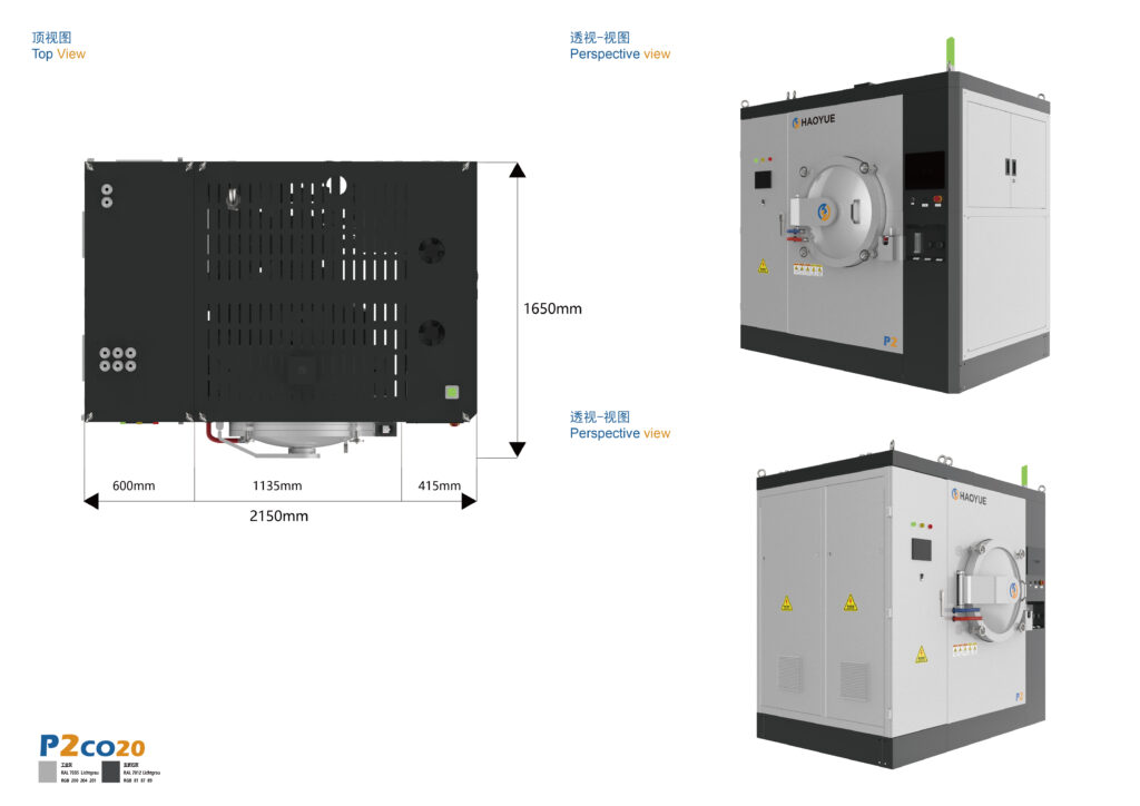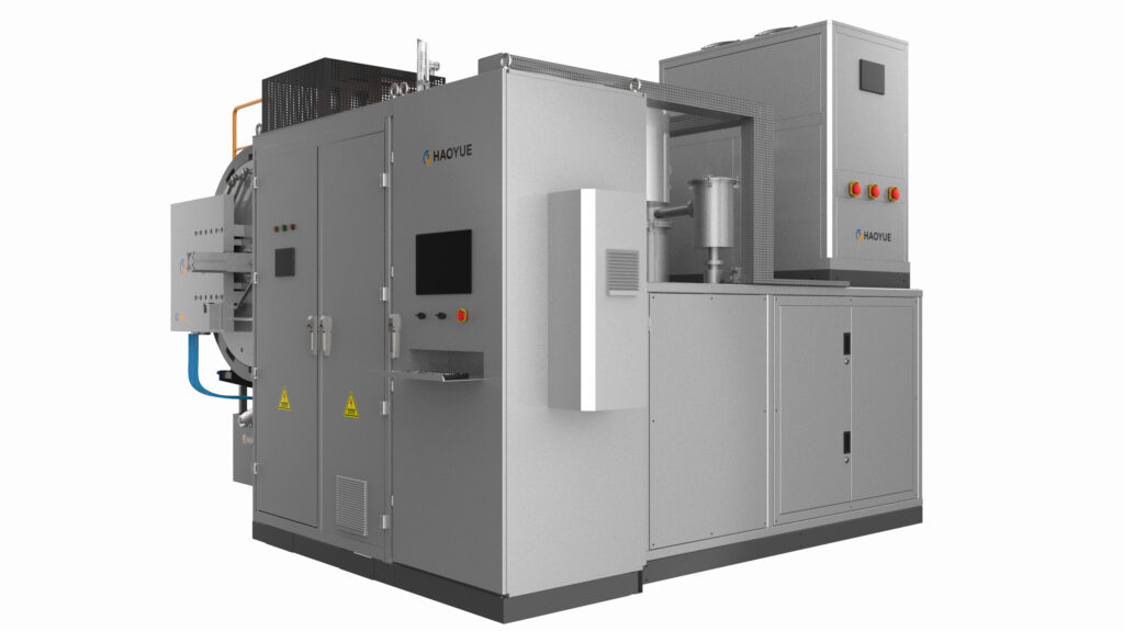






A vacuum hot press furnace is a vacuum furnace that applies uniaxial mechanical pressure to a powder compact or preform through a die set while it is heated, which lets the material reach full density at a lower temperature or in a shorter time than pressureless sintering would require. Everything else in this guide follows from that sentence, including the part most buyers get wrong: what actually needs to be specified.
Search interest in custom hot pressing furnaces is easy to explain. Hot pressing is one of the few densification routes where the machine has to be matched to the part, not the other way round. Unlike a general-purpose vacuum sintering furnace — where you pick a chamber size and a temperature rating and move on — a hot press is sized from three numbers that come from your material and your part geometry: the pressure your powder needs, the projected area that pressure acts on, and the temperature at which densification actually happens.
This article is written for engineers and procurement teams who have a material in hand and need to turn it into an enquiry that a manufacturer can quote accurately on the first pass.
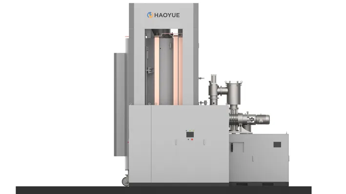
What Is a Vacuum Hot Press Furnace?
A hot press combines three systems that are usually bought separately:
- A vacuum vessel and hot zone that provides a controlled atmosphere and temperatures up to 2200 °C in our P-series range.
- A hydraulic force system that drives one or two rams into a die set, with force held to better than ±3% across the stroke.
- A die or tooling set — in practice usually graphite — that transmits pressure to the powder and defines the final part shape.
The word custom in “custom hot pressing furnace” usually does not mean the furnace is exotic. It means the die, the ram stroke, the pressure profile, and the usable working envelope have to be reconciled with your part. The furnace is the constant; the tooling is the variable. Enquiries that treat the die as an afterthought tend to come back either over-specified or unusable.
Hot pressing sits between two neighbouring processes. Pressureless sintering applies heat only. Hot isostatic pressing applies heat and pressure from all directions simultaneously through a gas medium. Hot pressing applies heat and directional pressure through solid tooling, which is why it produces near-net-shape parts with minimal subsequent machining — and why part size is bounded by die and ram capacity rather than by the vessel alone.
How a Vacuum Hot Press Furnace Works
Stage 1 — Die loading and evacuation
The powder or preform is loaded into the die, the die is placed on the lower ram, and the chamber is evacuated. This is a slower step than it looks: powders carry adsorbed moisture and, in the case of milled or binder-treated feedstock, a substantial gas load. Our P-series vacuum specification is either 1 Pa or 6.7 × 10⁻³ Pa depending on the pump package, and the choice is a process decision, not a cosmetic one — see the note on vacuum below.
Stage 2 — Heating and pressure application
Three pressure strategies are in common use, and the right one is a materials question:
- Cold pressing followed by heating under load — simplest to control, used when green strength is adequate.
- Heating first, then applying pressure at temperature — used when the powder must be degassed or reduced before densification begins.
- Staged or ramped pressure — pressure rises as the material softens, which limits early die wall friction and improves density distribution in tall sections.
Ramp rates on our P-series units are 1–10 °C/min below 1600 °C and 1–15 °C/min above 1600 °C. Those limits exist to control thermal gradient through the die and the part, not because the heating elements are the constraint.
Stage 3 — Dwell under pressure
Peak temperature, applied pressure, and dwell time form one coupled decision. Holding longer is not free: grain coarsening, die degradation, and, for some systems, unwanted reaction with the die all accelerate at the top of the range. Ram displacement is the most useful in-process signal available — the displacement trace records shrinkage as it happens, and a flattening curve is a practical indication that densification has stopped.
Stage 4 — Controlled release and cooling
Pressure release, cooling rate, and part removal are where cracked parts and distorted dies usually originate. Our P-series units use bellows-sealed upper and lower rams so that both can move under vacuum, and an optional 2 bar gas quench is available where cycle time or as-cooled microstructure justifies it.
How to Specify One: The Numbers That Matter
Step 1 — Start from the part, not the catalogue
Define the finished part first: projected area, section height, target density, and tolerance-critical surfaces. Everything downstream is derived from these.
Step 2 — Convert pressure requirement into force
Hot pressing pressure is usually established empirically for a given powder — it is a property of your material system, not a figure that appears in a furnace catalogue. Once the required pressure per unit area is known, force follows directly from projected area, with an allowance for die wall friction and material lost to the die clearance. This arithmetic, not the sample diameter, is what determines which tonnage column you land in: our units span 100 ton (P3VGR22) to 1200 ton (P11VGR22).
A practical consequence worth stating plainly: oversizing tonnage is not free. Larger force capacity brings a larger ram, a larger frame, a larger vacuum vessel, and higher operating cost per cycle. Size to the part you have plus a documented roadmap, not to the largest part you can imagine.
Step 3 — Match the die envelope to the chamber
Each P-series model has both a chamber dimension and a usable sample diameter. The sample column is the binding one for hot pressing work:
| Model | Chamber (mm) | Usable sample dia. | Press force | Max temperature |
|---|---|---|---|---|
| P3VGR22 | Φ300 × 400 | Φ150 | 100 ton | 2200 °C |
| P5VGR22 | Φ500 × 700 | Φ300 | 300 ton | 2200 °C |
| P7VGR22 | Φ700 × 900 | Φ400 | 600 ton | 2200 °C |
| P9VGR22 | Φ900 × 900 | Φ500 | 800 ton | 2200 °C |
| P11VGR22 | Φ1100 × 900 | Φ600 | 1200 ton | 2200 °C |
Step 4 — Choose the vacuum package deliberately
The two vacuum configurations available on P5 through P11 are 1 Pa or 6.7 × 10⁻³ Pa, and these are pump configurations, not a tolerance band. 1 Pa is a mechanical-pump rough-vacuum level with no diffusion or molecular pump fitted. 6.7 × 10⁻³ Pa is the high-vacuum configuration, reached with a diffusion pump or molecular pump. P3VGR22 is specified at 6.7 × 10⁻² Pa.
If your process is sensitive to oxygen, nitrogen, or moisture — common for non-oxide ceramics, refractory metals, and fine reactive powders — specify the pump package explicitly at purchase. Retrofitting high vacuum later is more disruptive than specifying it up front.
Step 5 — Decide between single and dual chamber
For development work or short runs, a single chamber is correct and cheaper. For recurring production, our dual-chamber configuration (P5VTGR22-II, P7VTGR22-II) shares one vacuum system, fast-cooling circuit, furnace body and control system between two chambers, with a vertical side-opening door and a 400 mm total-stroke twin-ram. It reduces both capital per unit of output and floor area.
| Model | Chamber (mm) | Usable sample dia. | Press force | Max temperature |
|---|---|---|---|---|
| P5VTGR22-II | Φ500 × 700 | Φ300 | 300 ton | 2200 °C |
| P7VTGR22-II | Φ700 × 900 | Φ400 | 600 ton | 2200 °C |
Key Parameters
| Parameter | Specification | Why it matters |
|---|---|---|
| Maximum temperature | 2200 °C | Sets which material systems are reachable |
| Press force | 100 – 1200 ton | Derived from required pressure × part area |
| Force accuracy | Better than ±3% | Repeatability of density from part to part |
| Ultimate vacuum | 6.7 × 10⁻² Pa (P3); 1 Pa or 6.7 × 10⁻³ Pa by pump package (P5–P11) | A pump configuration choice, not a precision claim |
| Heating rate | 1–10 °C/min (< 1600 °C); 1–15 °C/min (> 1600 °C) | Gradient control through die and part |
| Temperature uniformity | ±5 °C (5-point survey, 1000 °C, 2 h hold) | The acceptance-test number to ask for |
| Ram sealing | Bellows-sealed upper and lower rams | Both platens move under vacuum |
| Cooling | Vacuum cooling; optional 2 bar gas quench | Cycle time and as-cooled microstructure |
| Ram stroke (dual chamber) | 400 mm total, twin-ram | Die height and part ejection envelope |
| Control | Industrial PC + PLC + PID, multi-zone | Recipe repeatability and data traceability |
Vacuum Hot Press vs. Alternative Densification Routes
| Route | Pressure mode | Our specification | Choose it when | Avoid it when |
|---|---|---|---|---|
| Hot press (P series) | Uniaxial, via tooling | 100–1200 ton, 2200 °C, to ±3% force | Discs, plates, near-net-shape blocks; Si₃N₄, SiC, B₄C, BN, low-cobalt cemented carbide; systems needing directional pressure | Complex 3D shapes, undercut features, or very large aspect ratios that jam in a die |
| Pressureless vacuum sintering (V series) | None | Up to 2400 °C (graphite hot zone), 6.7 × 10⁻³ Pa | Powder metallurgy, debind-and-sinter, parts where die cost is unjustified | Target density cannot be reached without applied pressure |
| Gas pressure sintering (G series) | Isostatic gas, 6 or 10 MPa | 1600 / 2000 °C, 10 Pa | Batch production of geometrically complex parts; Si₃N₄ balls and cutting tools | You need 2200 °C, or uniaxial pressure specifically |
| Hot isostatic pressing (I series) | Isostatic gas, 100 / 150 / 200 MPa | 2000 °C (C/C hot zone) or 1400 °C (molybdenum) | Full densification of complex shapes, castings consolidation, diffusion bonding | Budget is constrained, or near-net-shape tooling economics are better |
| Spark plasma sintering (S series) | Uniaxial, pulsed-current heated | Up to 300 °C/min, 2200 °C, 1 Pa | Nanostructure retention, fast development cycles, difficult-to-sinter compositions | Large parts, or capital per kilogram must stay low |
A note on the SPS vacuum figure: 1 Pa is a mechanical-pump rough-vacuum configuration with no diffusion or molecular pump. SPS is chosen for its heating rate and its ability to retain fine microstructures, not for vacuum level.
Applications
Hot pressing earns its place when heat alone cannot close porosity, or when the temperature needed to do so would coarsen the microstructure. In our own range, the P series is used for:
- Non-oxide structural ceramics — silicon nitride, silicon carbide, boron carbide, boron nitride — where directional pressure substitutes for sintering additives that would otherwise degrade high-temperature properties.
- Cemented carbide with reduced binder content, where higher hardness is wanted without sacrificing density.
- High-temperature alloys for engine and turbine-adjacent applications.
- Composites and near-net-shape components, including Nb oxides, copper- and iron-based powder materials, and high-thermal-conductivity systems.
- Large flat sections such as aircraft brake discs and armour plate, where the combination of 2200 °C capability and high tonnage is the enabling factor.
Corresponding downstream industries: engines and powertrain, cutting tools, corrosion-resistant machinery, and aerospace structures.
Limitations: When Not to Choose a Vacuum Hot Press
- Complex geometry. Hot pressing produces discs, plates, rings, and simple blocks. Undercuts, internal channels, and thin tall walls belong with gas pressure sintering or HIP, or with pressureless sintering plus machining.
- Parts that exceed the die economics. If the part is large and simple and the run is long, a die that survives the cycle may cost more per cycle than the value added.
- Very high aspect ratios. Tall thin sections suffer die wall friction and uneven density from top to bottom.
- Materials that react with graphite tooling. If the die chemistry is incompatible, either the tooling material changes or the process changes. Ask before assuming.
- Processes above 2200 °C. That is the top of our hot press range; a different technology is required, not a larger press.
- High-throughput small parts. Continuous or multi-station configurations — available in our SPS range — are usually the better specification for high-volume small components.
- Hard boundaries on atmosphere. Hot pressing runs under vacuum or inert gas. Graphite tooling excludes oxidising atmospheres at temperature, and hydrogen work belongs on a hydrogen furnace with a molybdenum hot zone.
FAQ
What is a vacuum hot press furnace used for?
A vacuum hot press furnace densifies powders and preforms that will not reach full density by heat alone. In our range, typical work includes silicon nitride, silicon carbide, boron carbide, boron nitride, low-cobalt cemented carbide, high-temperature alloys, and near-net-shape composite parts such as brake discs and armour plate.
How much pressure does hot pressing need?
The pressure requirement belongs to the material, not to the machine, and is normally determined by trial data for a given powder system. Once known, the required force follows from the projected area of the part, which is what determines tonnage: our range runs from 100 ton to 1200 ton.
What temperature can a vacuum hot press furnace reach?
Our P-series vacuum hot press furnaces are rated to 2200 °C, with temperature uniformity of ±5 °C measured on a five-point survey at 1000 °C held for two hours.
What vacuum level does a hot press achieve?
For our P series, it depends on the pump package. P3VGR22 is specified at 6.7 × 10⁻² Pa. P5 through P11 are offered at either 1 Pa or 6.7 × 10⁻³ Pa — 1 Pa being a mechanical-pump rough-vacuum configuration, and 6.7 × 10⁻³ Pa being the high-vacuum configuration requiring a diffusion or molecular pump.
Is hot pressing the same as HIP?
No. Hot pressing applies uniaxial pressure through solid tooling, which limits part shape to what can be ejected from a die. HIP applies isostatic pressure through gas in all directions, which suits complex geometries but without near-net-shape tooling economics.
When should I choose gas pressure sintering instead?
Choose gas pressure sintering when the parts are geometrically complex and produced in batch, and the process temperature stays within 1600 or 2000 °C — our G series runs at 6 or 10 MPa for exactly this case. Choose hot pressing when you need directional pressure or 2200 °C.
If you have a material system and a target density, send us the powder specification and part drawing. We will run trials on our own equipment and return the density, microstructure and cycle data before you commit to a specification.
Related equipment: P Series Graphite Vacuum Hot Pressing Furnace · G Series Gas Pressure Sintering Furnace · S2 SPS Sintering System