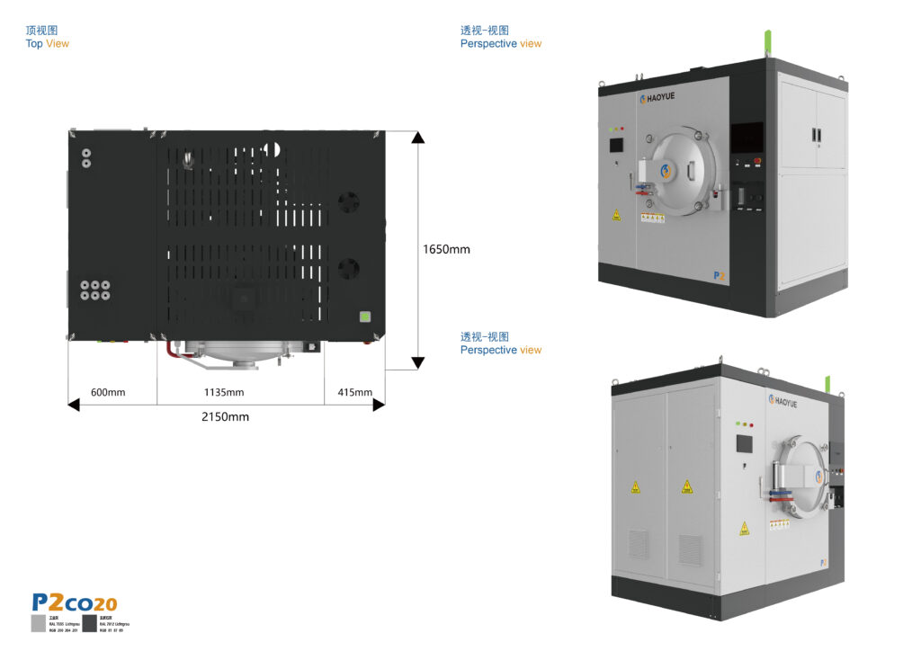
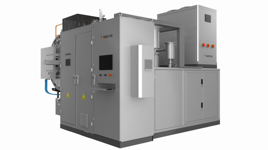
A vertical vacuum furnace is a vacuum-tight vessel whose hot zone and load axis stand upright, so the charge enters through the bottom or the top of the chamber rather than a side door. Orientation looks like a layout decision. It is really a decision about which seal you maintain, how long a part you can process, and where the cold spot lands.
Most requests open with chamber volume and maximum temperature. Those two numbers describe a vessel, not how an 800 × 800 × 1200 mm box chamber and a Φ650 × 1200 mm cylinder of similar volume behave on the floor.

What a vertical vacuum furnace is — and what it is not
Three load paths exist, and each one puts the sealing surface somewhere different:
- Bottom-load. The vessel stays fixed and the hearth, on a column or lift table, rises into the hot zone. The seal sits at the bottom flange, in the cold zone, where spalled insulation and drips fall away from it.
- Top-load. The vessel stays fixed and the lid lifts. The seal is at the top flange, and the load goes in from above by crane or hoist.
- Horizontal side-load. A box or cylindrical chamber with a door at the end or the side — the V series format, 300 × 300 × 400 mm through 800 × 800 × 1200 mm.
It is not a horizontal furnace with the door rotated 90°: the load becomes a column, the hearth support becomes a conduction path, the seal moves into a different thermal and contamination environment, and loading equipment joins the process cycle.
How it works, stage by stage
Stage 1 — Sealing at the cold end, and where the debris goes
On a bottom-load machine the seal face is protected by geometry: graphite dust, binder condensate and oxide flakes fall to the hearth or pit floor, not onto the O-ring. That is why vacuum brazing, metallizing and annealing of coated parts is so often run bottom-load.
On a top-load machine the seal faces upward, under the lid: condensate from a binder burn-off, or dust disturbed during loading, lands on the sealing surface. The lid is heavy, and compression depends on lid weight and on how the elastomer has taken a set. Wipe and inspect the groove every time the lid comes off.
Stage 2 — Heating a column instead of a box
In vacuum there is no convection worth modelling: heat arrives by radiation and leaves by conduction. A tall hot zone produces a predictable profile:
- The hearth support column conducts to the water-cooled bottom flange, so the bottom of the load runs cooler than the middle.
- The lid and its cooling ring sit close to the top of the insulation stack, so the top runs cooler as well.
- The middle runs hottest.
Tall hot zones are therefore split into separately trimmed zones, and acceptance is a five-point survey at 1000 °C — ±5 °C, held 1 h on the V series box chambers and 2 h on the hot presses. A long load also shades itself: the skin sees the heaters, the core sees only the skin. So soak time grows faster than wall thickness, and a Φ650 × 3200 mm charge needs a schedule written for its length, not copied from a 1200 mm one.
Stage 3 — Pressing along the same axis as gravity
A vertical hot press puts the ram axis vertical, in line with the load. The P series runs 2200 °C in a graphite hot zone, 100 to 1200 t of force at better than ±3% accuracy, chambers from Φ300 × 400 mm to Φ1100 × 900 mm, with 1–10 °C/min below 1600 °C and 1–15 °C/min above.
The consequence is mechanical: the load sits in pure axial compression, so a tall billet or stacked preform stays straight without lateral fixturing, and the pressed faces stay parallel by construction. Where a shop needs the same axis but separated heating and cooling, the double-chamber P5VTGR22-II and P7VTGR22-II share vacuum, cooling, vessel and controls, open at the side, and use a 400 mm total-stroke double-acting ram.
Stage 4 — Cooling a tall charge
Fast cooling at 2 bar is an option on these furnaces, and in a vertical chamber the gas path matters more than the pressure. Gas admitted at the top of a solid column short-circuits down the annulus between load and insulation, cooling the skin while the core lags. Hollow loads and spacer-stacked charges cool far more evenly than a solid billet of the same mass — a difference that shows up as distortion, not on a thermocouple.
Key parameters that orientation changes
| Parameter | What it controls | Vertical consequence |
|---|---|---|
| Seal location | Leak rate, maintenance interval | Bottom flange stays clean but is harder to reach; top flange is accessible but exposed to fallout |
| Hearth support | Cold spot at the load bottom | Single column conducts heat out; zone trim compensates, it does not remove it |
| Chamber height : diameter | Uniform zone, pump-down volume | Tall ratios add dead volume above the load and lengthen pump-down |
| Loading equipment | Cycle time, building height | Top-load needs hook height; bottom-load needs a pit or lift table |
| Zone count | ±5 °C at 1000 °C | Long hot zones need independent top / middle / bottom trim |
| Ram axis | Part straightness under load | Vertical pressing keeps tall parts in axial compression |
Vertical models we build
| Series | Model | Chamber (mm) | Load path | Hot zone | Vacuum | Max temp |
|---|---|---|---|---|---|---|
| H (vacuum hydrogen) | HV6S/120 | Φ650 × 1200 | Bottom | MO | 6.7×10⁻³ Pa | 1000 / 1300 °C |
| H (vacuum hydrogen) | HV6S/320 | Φ650 × 3200 | Top | MO | 6.7×10⁻³ Pa | 1000 / 1300 °C |
| G (gas pressure sintering) | G3V | Φ350 × 700 | Bottom | GR | 10 Pa | 1600 / 2000 °C, 6/10 MPa |
| G (gas pressure sintering) | G5V | Φ500 × 1000 | Bottom | GR | 10 Pa | 1600 / 2000 °C, 6/10 MPa |
| I (HIP) | I5CC20 | Φ500 × 1000 | Top | C/C | 100 Pa | 2000 °C, 100/150/200 MPa |
| I (HIP) | I10M014 | Φ1000 × 2000 | Top | MO | 100 Pa | 1400 °C, 100/150/200 MPa |
| P (hot press) | P3VGR22 → P11VGR22 | Φ300 × 400 → Φ1100 × 900 | Vertical ram | GR | 6.7×10⁻² Pa; 1 or 6.7×10⁻³ Pa on P5–P11 by pump set | 2200 °C, 100–1200 t |
Two rows are worth reading twice. On HV6S/320 at Φ650 × 3200 mm, orientation is not a preference: the part cannot enter through a side door. And on P5–P11 the vacuum figure is a pump-set choice, not a tolerance — 1 Pa is mechanical-pump class, 6.7×10⁻³ Pa needs a diffusion or molecular pump.
Bottom-load vs top-load vs horizontal chamber
| Criterion | Vertical bottom-load | Vertical top-load | Horizontal box chamber |
|---|---|---|---|
| Best load shape | Tall, heavy, single-piece | Long, light, crane-handled | Flat, wide, many pieces |
| Seal exposure | Low — debris falls away | High — lid face collects fallout | Medium — door sill collects dust |
| Building requirement | Pit or lift table | Hook height and crane | Floor space, no pit |
| Cold spot | Bottom, at the support column | Top, under the lid ring | Door end and hearth rails |
| Loading labour | One operator, guided | Rigging and crane time | Trolley or roller hearth |
| Typical limit hit first | Chamber height | Lid weight and seal | Part height |
The third column is not the lesser option. A V8GR24 box chamber at 800 × 800 × 1200 mm out-produces a Φ650 cylinder on flat plates, because the volume above a tall load is dead space. Orientation should follow the geometry you ship.
Applications where orientation decides the job
- Long tubes, rollers and shafts. Upright, they hang or stand straight; horizontally over a long span they sag at temperature and stay bent. HV6S/320 exists for this class of work.
- Glass-to-metal seals and metallized ceramic. Assemblies are fixtured upright so the seal does not run, and bottom-load keeps the flange seal clear of process debris.
- Tall hot-pressed billets and composite stacks. Axial compression and a vertical ram keep faces parallel without lateral fixturing.
- HIP of tall components. I10M014 at Φ1000 × 2000 mm and 100/150/200 MPa covers geometry that will not fit a squat chamber.
- Ceramic balls and cutting tools under gas pressure. G3V and G5V load from below at 6/10 MPa, 1600/2000 °C, with dewaxing, vacuum sintering, partial-pressure sintering and pressure sintering integrated in one cycle.
Limitations — when a vertical furnace is the wrong answer
- Flat, wide, high-count loads. Trays of plates or small parts waste most of a tall cylinder, and a pancake-shaped charge pays for hot zone and pumping volume it never uses. Take the box chamber.
- Throughput-limited production. One vertical load is one load at a time. If cycles per shift is the constraint, a double-chamber or continuous layout is the right frame.
- No pit and no crane. This stalls more projects than metallurgy does. Bottom-load needs a pit or lift table; top-load needs hook height. Check the building before the specification.
- Hydrogen service above the H series class. The H series runs 1000 / 1300 °C with a molybdenum hot zone at 6.7×10⁻³ Pa. Above that, the hot zone material — not the orientation — becomes the design problem, and it usually resolves to graphite in a different furnace class.
- Processes that need a horizontal quench transfer. If the metallurgy depends on moving the load into a separate cooling chamber, that architecture decides the layout first.
Related equipment
The orientations described here are built into four ranges. The V series graphite hot-zone vacuum furnace covers the horizontal box chambers from 300×300×400 to 1000×1000×1400 mm. The bottom-load G series is the G series vertical gas pressure sintering furnace, G3V at Φ350×700 mm and G5V at Φ500×1000 mm to 2000 °C under 6–10 MPa. Where the load also has to be pressed along the same upright axis, the P series graphite vacuum hot pressing furnace runs 2200 °C and 100–1200 t from Φ300×400 to Φ1100×900 mm, and tall HIP work belongs to the hot isostatic press range, the I10M014 taking Φ1000×2000 mm at 100/150/200 MPa.
FAQ
What is a vertical vacuum furnace used for?
Where the part is longer than it is wide: tubes, rollers, shafts, crucibles, tall billets, glass-to-metal assemblies and hot-pressed stacks. The upright axis lets the load stand or hang straight, and on bottom-load machines it keeps the seal out of the debris path.
Is bottom-load better than top-load?
For dirty processes and heavy loads, usually yes — the seal is protected and the lift does the work. Top-load wins when the part is light enough to crane and headroom exists but floor space does not. Seal exposure, rigging time and building geometry decide it.
Can a vertical furnace do hot pressing?
Yes. The P series is a vertical hot press: 2200 °C, 100–1200 t, force accuracy better than ±3%, chambers from Φ300 × 400 mm to Φ1100 × 900 mm, optional 2 bar fast cool. The vertical ram keeps tall parts in axial compression, which suits billets and composite stacks.
How long a part can a vertical vacuum furnace take?
The hot zone height sets the limit, not the vessel. Our top-load HV6S/320 takes a Φ650 × 3200 mm charge — a length no side-door chamber of that diameter accepts. Below that, uniformity and soak time become the constraints before clearance does.
Does a vertical chamber still hold ±5 °C?
It can, certified the same way as any other: a five-point survey at 1000 °C, held 1 h on the V series and 2 h on the hot presses. A tall hot zone needs independent top, middle and bottom trim to get there, and is re-surveyed after any heater or insulation change.
What vacuum can a vertical furnace reach?
The class is set by the pump set. 6.7×10⁻³ Pa on the H series is a diffusion- or molecular-pumped configuration; 10 Pa on the G series vertical models is a mechanical-pump class; 100 Pa on the HIP models reflects pressure-vessel duty. On P5–P11 the choice between 1 Pa and 6.7×10⁻³ Pa is a pump-set option at order.