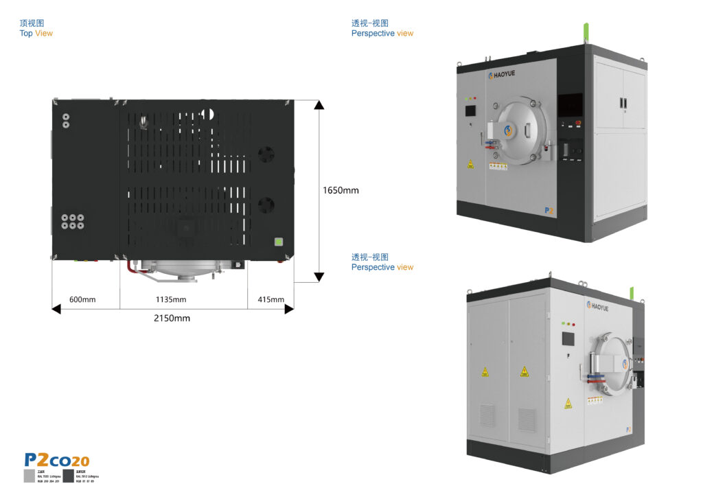
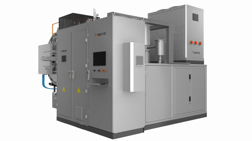
A cemented carbide sintering furnace is a vacuum or pressure vessel that densifies tungsten carbide–cobalt compacts by forming a cobalt-rich liquid phase at roughly 1380–1480 °C while holding the carbon activity of the atmosphere inside a very narrow window. It is not a hot oven with a pump attached; it is a chemical reactor whose gas phase decides whether your insert comes out tough, brittle, or quietly porous.
Most carbide yield complaints we are asked about do not start in the powder or the press. They start in three places the furnace owns: the dewaxing vent, the temperature spread across the load when cobalt turns liquid, and the cooling slope. This is for engineers and procurement teams specifying a cemented carbide sintering furnace: the mechanism, the parameters that move yield, the routes we build, and when to buy something else.

What is a cemented carbide sintering furnace?
A cemented carbide sintering furnace is a controlled-atmosphere furnace that runs a pressed WC-Co compact through binder removal, solid-state densification, densification in a cobalt liquid phase, an optional pressure stage and a controlled cool-down, using vacuum or overpressure gas to remove oxygen and collapse porosity.
Three physical facts drive every design decision:
- Cobalt is the densification agent, not the carbide. WC skeletons do not reach full density alone at usable temperatures; cobalt forms a liquid phase at typically 1300–1400 °C depending on carbon content and Co fraction, and capillary forces pull the skeleton together within minutes.
- Carbon content is a state variable, not a specification. Below the window you form brittle η phase (W₃Co₃C); above it, free graphite appears as soft spots and poor wear resistance.
- Porosity closes once. Residual pores must collapse while cobalt is liquid. Pressure that arrives late, or a load that cools unevenly, freezes that porosity in permanently.
How it works: the five stages that matter
Stage 1 — Binder removal (roughly 200–500 °C, typical)
Pressed parts carry paraffin, PEG or a polymer lubricant at typically 2–3 wt%. Removal is slow and volumetric, and the gas flow must carry vapour out of the hot zone before it re-condenses.
This is where quiet failures happen. Binder vapour condensing on a cooler part leaves a carbon-rich patch that sinters into a soft spot, visible only after grinding. The fix is a slower ramp, a positive gas sweep, and a vent path that does not pass over cold tooling — not more temperature. The lowest programmable ramp on our V-series graphite furnaces is 1 °C/min, the range you want here. On the G series, dewaxing runs under positive pressure with an integrated wax-removal path, so the vessel continues straight into vacuum sintering.
Stage 2 — Vacuum heat-up and solid-state necking (to roughly 1200–1300 °C)
The compact is still an open-pore body, and vacuum now does chemical work: stripping residual oxygen, water vapour and nitrogen from the pore network before they react with carbon.
Vacuum here is a pump configuration, not a precision figure. 6.7×10⁻³ Pa means a diffusion or molecular pump is fitted — the high-vacuum configuration we specify on V-series graphite hot zones. 10 Pa is the G-series pressure-sintering configuration, where the vessel is backfilled with argon anyway. 1 Pa is mechanical pump only, adequate for SPS and oxygen-insensitive work, not for carbide. A graphite hot zone at 6.7×10⁻³ Pa is also mildly carbon-buffering: CO/CO₂ equilibrium suppresses decarburisation rather than causing it, inverting the logic of refractory metals where the same graphite is a contamination source.
Stage 3 — Liquid-phase hold (roughly 1380–1480 °C, typical)
Cobalt melts, capillary pressure collapses the pore network, and shrinkage finishes in minutes. Hold is short by design — typically 30–60 minutes for conventional WC-Co; longer holds buy nothing and cost grain growth and cobalt loss.
What the furnace must deliver here is not peak temperature but uniformity at peak temperature. A 15 °C spread across a 600 mm load is a 15 °C spread in liquid-phase fraction, and therefore in cobalt content, grain size and hardness from tray to tray. Our published figure is ±5 °C by five-point measurement at 1000 °C held one hour — note the qualification temperature, because radiation-dominated heat transfer at 1450 °C behaves differently. Ask for that temperature and the load geometry, not just the ± number.
Stage 4 — Pressure stage (0 to 6/10 MPa, or a separate HIP cycle)
Pressure only works in a defined window. Applied too early, the compact still has open porosity and the gas simply equalises inside it. Applied at the right moment, with pores just closed and cobalt still liquid, argon at 6 MPa (or 10 MPa in the higher G-series configuration) collapses remaining closed porosity. Applied after solidification, pressure only stresses the part.
A G-series gas pressure sintering furnace does this in one cycle: dewax, vacuum sinter, partial-pressure sinter, pressure sinter at 6/10 MPa, controlled cooling. An I-series HIP vessel does it at 100/150/200 MPa on an already-sintered part — a different economic proposition that requires dense or encapsulated parts.
Stage 5 — Controlled cooling
Cooling is where cobalt moves. Slow cooling through roughly 1200–800 °C lets cobalt migrate along the thermal gradient toward the surface, producing a cobalt-enriched skin and depleted core — visible as cobalt lakes, or as hardness that fails on the outside while passing in the middle. Faster cooling suppresses segregation but adds thermal stress — a grade-specific compromise, which is why our V, P and D series offer optional 2 bar gas fast cooling.
Key parameters and where they go wrong
| Parameter | Typical setting for WC-Co | What it controls | Common failure if wrong |
|---|---|---|---|
| Dewaxing window | 200–500 °C, slow ramp with gas sweep | Carbon pickup, stains, blisters | Condensed binder re-deposits carbon; soft spots after grind |
| Vacuum at heat-up | 6.7×10⁻³ Pa (diffusion/molecular pump) | Oxygen and water removal before liquid phase | Residual O₂ reacts with C; η phase at surface |
| Sintering temperature | 1380–1480 °C (grade dependent) | Liquid-phase fraction, densification, grain growth | Low → residual porosity; high → coarsening, Co loss |
| Hold at temperature | 30–60 min (typical) | Pore closure vs grain growth | Long hold degrades hardness with no density gain |
| Uniformity at hold | ±5 °C qualified at 1000 °C, five-point | Consistency tray-to-tray | Hardness and Co gradient across the load |
| Pressure stage | 6/10 MPa argon (G series); 100/150/200 MPa (I series) | Collapse of closed porosity | Before pore closure → no effect; after solidification → no effect |
| Cooling rate | Grade-specific; optional 2 bar fast cooling | Cobalt segregation, thermal stress | Slow → Co pooling; fast → cracking on thick sections |
Machine routes we build for carbide
Selected models from our current range; all figures are published catalogue specifications. The route depends on section thickness, grade, and whether porosity below metallographic detection is contractual.
| Route | Model range | Hot zone | Chamber (mm) | Vacuum | Max temperature | Pressure |
|---|---|---|---|---|---|---|
| Vacuum sintering (no pressure) | V3GR24 / V4GR24 / V6GR24 / V7GR24 / V8GR24 | Graphite (GR) | 300×300×400 → 800×800×1200 | 6.7×10⁻³ Pa | 2000 / 2400 °C | — |
| Gas pressure sintering / sinter-HIP | G3H / G9H | Graphite (GR), horizontal, side door | 300×300×1000 / 500×500×1800 | 10 Pa | 1600 / 2000 °C | 6 / 10 MPa |
| Gas pressure sintering, vertical load | G3V / G5V | Graphite (GR), bottom load | Φ350×700 / Φ500×1000 | 10 Pa | 1600 / 2000 °C | 6 / 10 MPa |
| Separate HIP (post-sinter densification) | I5CC20 | C/C | Φ500×1000 | 100 Pa | 2000 °C | 100 / 150 / 200 MPa |
| Separate HIP, large chamber | I10M014 | Molybdenum (MO) | Φ1000×2000 | 100 Pa | 1400 °C | 100 / 150 / 200 MPa |
| Hot pressing (low-cobalt / near-net shape) | P3VGR22 → P11VGR22 | Graphite (GR) | Φ300×400 → Φ1100×900 | 6.7×10⁻² Pa (P3); 1 or 6.7×10⁻³ Pa by pump configuration (P5–P11) | 2200 °C | 100–1200 t mechanical |
Note two numbers: the V-series graphite furnace reaches 2000/2400 °C, so the hot zone is never worked near its limit at 1450 °C, while the molybdenum and H-series ceiling of 1300 °C sits below the WC-Co window — those platforms serve cobalt removal and brazing, not sintering.
Graphite hot zone: contamination source or carbon reservoir?
In refractory metal work the graphite hot zone is the enemy. For WC-Co the logic inverts: carbide needs carbon, and a graphite hot zone sits in a CO/CO₂ equilibrium that buffers the part against decarburisation.
What graphite brings is a moisture problem, not a carbon problem. Felt and insulation absorb water whenever the vessel opens, and it desorbs between roughly 200 and 600 °C — the window where you control carbon. So bake-out is a process step rather than maintenance, it must not be combined with dewaxing, and pump-down time is a quality record.
Cemented carbide sintering vs alternative processes
| Process | Densification mechanism | Typical use | Why not use it for carbide |
|---|---|---|---|
| Vacuum sintering (V series, graphite) | Cobalt liquid phase, no applied pressure | Inserts, rods, wear parts, 6–12% Co | Cannot reliably close the last fraction of a percent in thick sections |
| Gas pressure sintering / sinter-HIP (G series) | Liquid phase + 6/10 MPa argon after pore closure | Mining tools, rolls, thick-section wear parts | Higher capital cost; overkill for thin simple inserts |
| Separate HIP (I series) | 100–200 MPa argon on a densified part | Fatigue-critical and aerospace carbide | Needs dense or encapsulated parts; extra thermal cycle |
| Hot pressing (P series) | Uniaxial pressure, 100–1200 t | Low-cobalt grades, near-net shapes, large discs | Shape limited by die; lower productivity |
| SPS / field-assisted (S series) | Pulsed current, 1 Pa mechanical-pump vacuum, up to 300 °C/min | R&D, ultrafine and binderless grades | Small samples (Φ80–Φ400); not a volume route for inserts |
| Hydrogen sintering (H series) | Reducing atmosphere, no pressure | Cobalt removal, annealing, brazing to steel | 1300 °C ceiling — below the WC-Co liquid-phase window |
Applications
- Metal-cutting inserts — turning, milling and drilling grades; the volume case for sinter-HIP when porosity specification is tight.
- Solid carbide rods and drills — slender sections where cooling control matters more than pressure.
- Mining, construction and DTH tools — button bits and picks; thick sections that need the pressure stage.
- Oil and gas drill bit inserts — high-cobalt tough grades where cobalt segregation on cooling is the dominant defect.
- Wear parts — dies, rolls, seal rings, nozzles; low-cobalt or graded parts push toward hot pressing.
Adjacent work on the same platforms: brazing carbide tips to steel in D-series diffusion bonding furnaces at 1400 °C.
Limitations: when a carbide sintering furnace is the wrong purchase
We would rather lose the order than sell a vessel that cannot do the job.
- Your hard phase contains nitrogen. Ti(C,N) cermets need controlled nitrogen partial pressure, not a carbon-buffered vacuum.
- Your section is under 10 mm and your porosity spec is loose. Pressureless V-series sintering is the economical answer; sinter-HIP will not improve a part that already meets spec.
- You need binderless or ultrafine grades. SPS gives 300 °C/min and grain-growth control a radiant-heated vessel cannot match, at the price of small samples.
- Your problem is dimensional, not densification. Shrinkage scatter traces back to compact density gradients, lubricant distribution or die wear. No furnace fixes a bad compact.
- You are assuming our ±5 °C applies at 1450 °C. It is a 1000 °C qualification. Ask for uniformity data at your hold temperature and load.
Related equipment
For pressureless WC-Co sintering the platform is the V series graphite vacuum sintering furnace range — 6.7×10⁻³ Pa from a diffusion or molecular pump, 2000/2400 °C, chambers from 300×300×400 to 800×800×1200 mm. Where the porosity specification requires a pressure stage, the G series horizontal gas pressure sintering furnace runs dewaxing, vacuum sintering, partial-pressure sintering and 6/10 MPa argon in one cycle. For fatigue-critical parts that need 100–200 MPa on an already densified insert, the I series hot isostatic press range is the separate HIP route.
FAQ
What temperature does a cemented carbide sintering furnace run at?
For conventional WC-Co the liquid-phase hold is typically 1380–1480 °C, with 30–60 minutes at temperature. Our graphite-hot-zone V-series furnaces are rated to 2000/2400 °C, so the working point sits well inside capability.
Do I need a sinter-HIP furnace or is vacuum sintering enough?
It depends on section thickness and your porosity criterion. Thin inserts in the 6–12% Co range often meet spec with pressureless sintering; thick sections and fatigue-critical parts usually need the 6/10 MPa stage, after pore closure but before cobalt solidifies.
What vacuum level is required?
6.7×10⁻³ Pa in a diffusion- or molecular-pumped configuration, as specified on our V-series graphite furnaces. That is a pump-configuration figure: a mechanical-pump-only vessel at 1 Pa is a different machine for a different job.
Why does my carbide come out with a brittle surface layer?
Usually decarburisation or η-phase formation, and usually upstream of the sintering hold. Check hot-zone moisture, pump-down leaks, and whether the dewaxing vent carries binder vapour back across the load.
Can one furnace do dewaxing and sintering?
Yes. The G series runs positive-pressure wax removal, vacuum sintering, partial-pressure sintering and pressure sintering in one vessel. The trade-off is cycle time.
How do I compare two suppliers’ uniformity claims?
Ask for qualification temperature, number of points, hold time and load geometry. A five-point ±5 °C figure at 1000 °C for one hour does not transfer to 1450 °C.