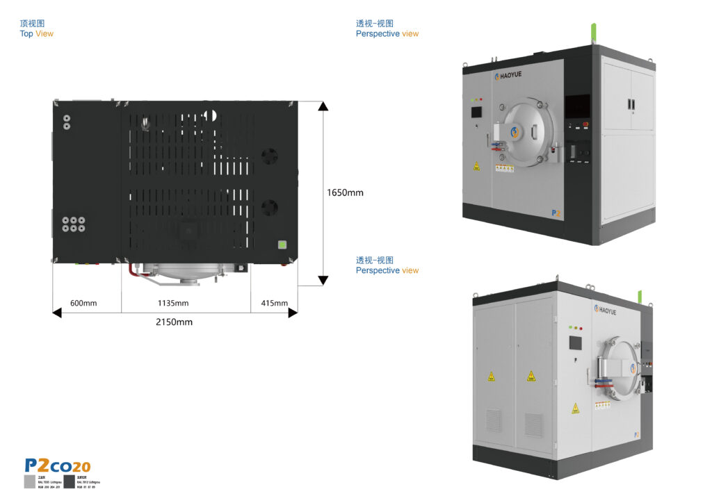
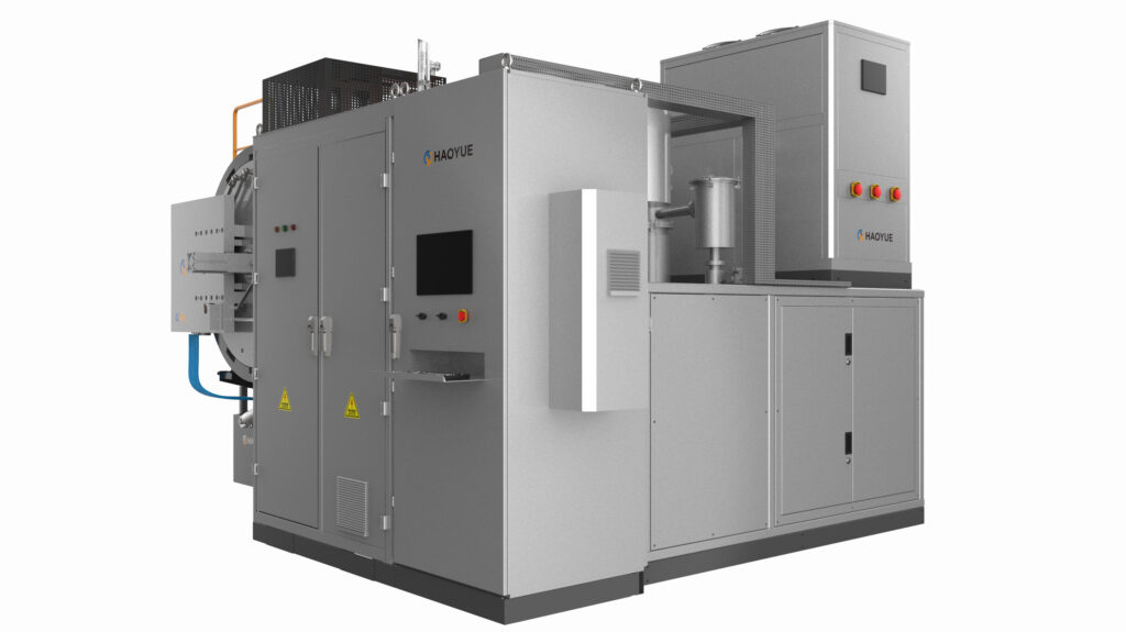
A continuous spark plasma sintering system is a multi-station SPS platform in which powder filling, pulsed-current heating under uniaxial pressure, and controlled cooling happen at separate stations simultaneously, so the power supply and press frame never sit idle waiting for a die to cool. It converts spark plasma sintering from a per-sample laboratory cycle into a takt-driven line, and moves the engineering problem from “can we reach 2200 °C” to “can we hold the same density at every station, every shift.”
That shift is the whole story. Teams evaluating SPS hit one wall, and it is not a temperature wall but a calendar wall: twenty minutes under current, four hours cooling, and the machine is paid for by the hour.

What a continuous SPS actually is — and what it is not
SPS, also called field-assisted sintering technology (FAST), passes a pulsed direct current through a graphite die and punches. The die is heating element, pressure vessel and shape tool at once, so densification takes minutes rather than hours: heat is generated inside the tooling, not radiated into it.
A batch machine does all of this in one chamber. A continuous spark plasma sintering system splits it into parallel stations:
- Station 1 — dosing. Powder goes straight into the die. No pre-compaction, no green body, no binder.
- Station 2 — heated pressing. Pulsed DC plus uniaxial force, ramp and hold.
- Station 3 — cooling. The loaded die leaves the current path and cools under vacuum or inert gas.
- Station 4 — ejection and die return. Part out, die cleaned and recharged.
Only Station 2 consumes power and press capacity. That is the entire economic argument — and everything below is the price you pay for it.
How the process runs, stage by stage
Stage 1: dosing without preforming
Conventional powder metallurgy presses a green body first, because a sintering furnace cannot tolerate loose powder. SPS needs no such step: the die is already the pressure vessel. Removing preforming removes a press, a tooling set, a handling step and a source of part-to-part variation.
The trade-off is that fill uniformity now controls part uniformity — a 2 % fill-height variation across a Φ150 mm die becomes a 2 % mass variation, and at fixed punch travel a thickness variation.
Stage 2: the heated station
Current passes through the punch–die–part stack, and where the heat is generated depends on what you sinter:
- Conductive powders (WC-Co, Cu, Ti, Mo, W, steel) carry a share of the current themselves. Heating is partly direct, and contact resistance at the punch faces matters.
- Insulating powders (Al₂O₃, ZrO₂, Si₃N₄, AlN) carry almost none. The die heats, and the part is heated inward by conduction from the die wall.
That is why recipes do not transfer between a carbide insert and an alumina disc. Our continuous stations are specified to 2200 °C and up to 200 °C/min, with ±3 % force accuracy and dual sensing — K-type thermocouple low range, infrared pyrometer high range, since neither is trustworthy across the full span.
Stage 3: cooling off the current path
Cooling is where batch SPS loses its day. A graphite die stack at 2000 °C cannot be quenched; it radiates, and radiation is slow, so in a single chamber the die, the part and the frame all wait. Moving the loaded die to a separate cooling station changes the constraint from “wait for the die” to “match the cooling curve to the metallurgy” — a defined rate through the cobalt liquidus for WC-Co, no thermal shock gradient across the part for ceramics.
The die returns to dosing. Turnaround — cool, clean the bore, inspect punch-seat erosion — sets the real floor on cycle time, and four heating stations feeding one slow cleaning bench is one effective station.
Where the cycle time actually goes
Illustrative arithmetic, not a rating: an 8-minute hold plus 12 minutes of transfer, evacuation and ramp gives a 20-minute station cycle — roughly three parts per hour per station, six with two stations. A four-hour cooling station then needs twelve dies in flight, which is why tooling count, not floor space, binds the layout.
Three consequences follow, and they cut against the sales narrative:
- Continuous SPS raises throughput by removing idle time, not by sintering faster. Hold time is set by diffusion and by the powder.
- Capital migrates from the press into the tooling. Dies in flight are dies you paid for.
- Yield risk concentrates at the interfaces — dosing, transfer, ejection — not in the hot zone.
Key parameters
| Parameter | S-150C | S-200C | Notes |
|---|---|---|---|
| Part diameter | Φ150 mm | Φ200 mm | Single-axis; simple solids |
| Pressing force | 100 t | 200 t | Servo-hydraulic, ±3 % |
| Max temperature | 2200 °C | 2200 °C | Die-limited in practice |
| Max heating rate | 200 °C/min | 200 °C/min | Batch SPS frames reach 300 °C/min |
| Ultimate vacuum | 10 Pa | 10 Pa | Mechanical-pump level |
| Atmosphere | Vacuum / inert gas | Vacuum / inert gas | Purge governs oxide control |
| Preforming | Not required | Not required | Powder into die |
| Automation | Optional auto load/unload | Optional auto load/unload | Manual-to-auto costs real money |
The platform family around it
The continuous stations sit at the top of a progression, and picking the wrong rung is the commonest specifying error.
| Platform | Structure | Part size | Force | Vacuum | Cycle character |
|---|---|---|---|---|---|
| S-150 / S-200 | Single chamber, batch | Φ100–150 / Φ150–200 mm | 100 / 200 t | 1 Pa | One part at a time, heat and cool in chamber |
| S-150S / S-200S | Double chamber, semi-continuous | Φ150 / Φ200 mm | 100 / 200 t | 10 Pa | Heat in one chamber, cool in the second |
| S-150C / S-200C | Multi-station, continuous | Φ150 / Φ200 mm | 100 / 200 t | 10 Pa | Parallel stations, takt-driven |
| S-200D / S-300D / S-400D | Hybrid SPS + induction | Φ200 / Φ300 / Φ400 mm | 200 / 300 / 400 t | 5 Pa | Larger parts, flatter radial gradient |
| P3–P11 VGR22 | Vacuum hot pressing | Φ150–600 mm | 100–1200 t | 6.7×10⁻² Pa, or 1 / 6.7×10⁻³ Pa by pump set | Hours per cycle, larger envelopes |
Two boundaries matter. Above Φ200 mm, the hybrid induction-assisted series reaches Φ400 mm at 5 Pa and vacuum hot pressing goes further. And 10 Pa is a mechanical-pump vacuum, one step below the 1 Pa of the batch frames — a material needing the 6.7×10⁻³ Pa class belongs in a graphite hot-zone vacuum furnace, not a press.
Continuous SPS versus the alternatives
| Route | Densification driver | Typical hold | Porosity outcome | Where it wins |
|---|---|---|---|---|
| Batch SPS | Pulsed current + uniaxial force | Minutes | Closed, fine grain | Research, small lots, alloy screening |
| Continuous SPS | Same, stations in parallel | Minutes | Closed, fine grain, repeatable | Mid-volume simple parts, stable recipe |
| Vacuum hot pressing (P series) | Radiant heat + sustained force | Tens of minutes to hours | Closed | Large blanks, 2200 °C, low volume |
| Gas pressure sintering (G series) | Liquid phase + 6–10 MPa gas | Hours | Closed, near-theoretical | Si₃N₄ bearings, ceramic tools, volume |
| Sinter-HIP / HIP (I series) | 100–200 MPa isostatic gas | Hours | Closed, fatigue-critical | Aerospace, medical, PM consolidation |
| Vacuum sintering (V series) | Radiant heat, no pressure | Hours | Residual porosity without liquid phase | Carbides, MIM, C/C, general PM |
The honest positioning: continuous SPS competes with vacuum hot pressing on grain size and cycle time, and with GPS on grain size — not on cost per part. A shop making 200,000 carbide inserts a year belongs on GPS; one making 5,000–50,000 parts that cannot survive a two-hour hold is the natural customer.
Applications
SPS covers a broad material set, and the continuous format extends it to repetitive production:
- Hard materials — WC, TiC, B₄C, SiC, ZrC, VC, and WC-Co cermets where fine grain or graded cobalt is the point.
- Oxides — Al₂O₃, ZrO₂, MgO, mullite, TiO₂, HfO₂, including translucent grades.
- Nitrides and borides — Si₃N₄, AlN, TiN, TaN, TiB₂, ZrB₂, HfB₂, LaB₆.
- Metals and intermetallics — Fe, Cu, Al, Ni, Cr, Mo, W, Ti, Be; TiAl, NiAl, MoSi₂.
- Composites — Si₃N₄+Ni, Al₂O₃+Ni, ZrO₂+Ni, WC+Co+Fe, SUS+WC/Co.
Pull comes from cutting tools, aerospace, electronics and automotive turbo and wear parts. The common thread: a specification a long furnace cycle would violate — a grain-growth limit, a diffusion-sensitive interface, or a graded structure.
Limitations — when you should not buy one
When the material is oxygen-critical. A graphite die at 2000 °C in a 10 Pa mechanical-pump vacuum is a reducing environment: oxides can lose stoichiometry at the surface, and alumina may come out grey rather than white. If colour or oxygen content is specified, you need a hydrogen-capable or high-vacuum platform.
When the geometry is complex. Single-axis pressing means no undercuts, cross-holes or near-net shapes. SPS gives you a blank; grinding gives you a part.
When the part is bigger than Φ200 mm. Go to the hybrid induction-assisted series at Φ200–Φ400 mm, or to vacuum hot pressing for larger envelopes at the cost of cycle time.
When the volume is high and the material is forgiving. For WC-Co at six figures, or Si₃N₄ bearing balls, GPS at 6–10 MPa is cheaper per part and adequate. Continuous SPS is a microstructure play, not a cost play.
When nobody owns the recipe. A continuous line multiplies whatever variation is in the recipe by the number of stations. If the batch process still needs a hand at the pyrometer, automation will automate the inconsistency.
When 300 °C/min is genuinely required. The continuous platform is rated to 200 °C/min. If the system depends on the higher ramp, the batch frames reach 300 °C/min and throughput must be solved differently.
Related equipment
The continuous platform is the continuous sintering machine (SPS) range — S-150C and S-200C, Φ150 / Φ200 mm, 100 / 200 t, 2200 °C, 10 Pa, parallel dosing, heating and cooling stations. If the volume does not justify a line, the S2 batch and semi-continuous SPS frame runs the same recipe in one or two chambers. Material that needs the 6.7×10⁻³ Pa class belongs in the V series graphite hot-zone vacuum furnace, not a press.
FAQ
What throughput can a continuous SPS line realistically deliver?
Throughput is the station cycle divided by the number of heating stations: at 20 minutes, one station yields about three parts per hour, and parallel stations scale that linearly. Die count in flight, not cooling capacity, is usually the limit.
Does continuous SPS still require pre-compacted powder?
No. Powder is filled directly into the die, so there is no preforming step and no green body. Fill uniformity then becomes the dominant quality variable.
Is 10 Pa vacuum enough for oxide ceramics?
It is a mechanical-pump vacuum — adequate for many carbides, borides and metals under inert purge, marginal for stoichiometry-sensitive oxides in a graphite die. If oxygen content or colour is specified, treat it as a limitation.
Can it produce near-net shapes?
Cylindrical or rectangular blanks with parallel faces; holes, threads and undercuts are machined afterwards. The value is in microstructure and cycle time, not shape complexity.
How long does a graphite die last, and what does it cost per part?
Die life depends on thermal cycling, punch-seat erosion and grade, and is not a published constant — any supplier quoting a fixed cycle count without your material and geometry is guessing. Model it as a consumable and measure it over your first hundred parts.
Continuous SPS or sinter-HIP for WC-Co?
Sinter-HIP is the volume route: liquid-phase sintering plus gas pressure, hours per cycle, mature and cheap per part. Continuous SPS wins when grain size, cobalt distribution or a graded structure is the specification.
If you are weighing a continuous line against your batch cycle, send us the material grade, blank drawing and annual volume — we will tell you which number, grain size or cost per part, your specification actually depends on. Platform details: continuous sintering, batch and hybrid SPS frames, high-vacuum vacuum sintering range.